Technology

Brushless Motor
The brushless motor is the heart of the fan. It is constructed using high temp/high strength Neodymium magnets, hybrid ceramic bearings, stainless steel flux ring & multi-stranded "Litz" windings. The motor is very power dense, allowing for smaller construction, while generating high power. The operating life is conservatively rated at 30,000 hours. Please note, a typical brushed motor fan is rated at 2,000 hours. Brushless DC (BLDC) motors offer several advantages over brushed DC motors. BLDCs are lighter and more efficient than conventional brushed motors, therefore reducing the energy consumption of the vehicle. As a result, Saving Gas! The elimination of brushes in a BLDC significantly increases motor reliability, reduces noise, reduces heat and increases efficiency due to the elimination of friction between the brushes and the commutator. Brushed DC motors have a typical efficiency of 70-75%, while a brushless DC motor can achieve 96% efficiency, a +28% improvement.
While a brushed motor operates, sparks are created when the brushes rub against the commutator, this creates a fire hazard and produces EMI. BLDCs generate no sparks and significantly reduce interference emissions allowing for easier compliance with electromagnetic compatibility (EMC) requirements. Most modern vehicles incorporate computer controls in engine management and other general vehicle operations. Reducing electromagnetic interference (EMI) is critical for proper vehicle operation. The BLDC motor has permanent magnets and flux ring which rotate around a fixed armature or stator, eliminating the problems of connecting current to the moving armature via brushes. The stator consists of a multiphase copper coil windings (U V W in figure 1) on a laminated core, and the rotor consists of permanent magnet segments or a molded ferrite ring that is attached at one end to the motor’s shaft. The stator windings are fed with electric currents controlled in magnitude and sequence (commutated) with pulse width modulation (PWM) to effect rotation of the rotor element just as in a typical brushed motor. Back-electromagnetic force (BEMF) is used for rotor positioning. This eliminates the need for hall sensors chips in the motor to identify the rotors position. These sensors are prone to burning out which limit the reliability of a motor. Since there are no sensors in our motor, the BLDC motor is called "sensor-less". This "commutation" is controlled by the electronic control module (ECM). All brushless motors require an ECM for operation.

Electronic Control Module (ECM)
The Electronic Control Module (ECM) is constructed using Grade-0, Hi-Rel & Mil-Spec integrated circuits. Only the highest quality components are used to ensure reliability and high power throughput. The module is vacuum epoxy encapsulated using thermal conductive resins to promote heat dissipation and waterproofing. Its small, modular design allows for easy replacement. The estimated operating life is 9000 hours.

The electronic control module (ECM) replaces the brush/commutator assembly of the brushed DC motor, which continually switches the phase to the windings to keep the motor turning. The rotors position need to signal the ECM to determine the start of the next phase. Some BLDC motors (not ours) use sensor chips in the motor. Senor chips prone to burning out which will cause an early failure of the motor. Our motors signaled the rotors position using Back-Electro-Magnetic-Force (BEMF). BEMF works on the 'law of induction', or more specifically Lenz's law, which says that the magnetic field of any induced current opposes the charge that induces it. BEMF (sometimes called the counter electromotive force) can be detected by measuring the current flowing through each coil as the motor rotates. BEMF signals are need by the control processor to identify the rotors position vs. the stator and determine when to engage the next phase. The ECM is specially programmed to use these signals to run the motor efficiently. The controller performs these timed power distribution by using a solid-state circuit rather than the brush/commutator system. The controller needs to be placed in close proximity to the motor to properly calculate PWM based on the motor's position. All BLDCs require an electronic controller for operation.
The Fan
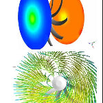
The axial fan impeller uses airfoil design that have a round leading edge, a sharp trailing edge, and in profile or cross section, look similar to a teardrop that has been flattened on one side. As air approaches the blade’s leading edge, the stream splits and travels above and below the blade. Air is deflected across the convex curve along the top of the blade and along the flat or concave curve on the bottom of the blade, and flows downward over the sharp trailing edge as it leaves the blade. According to Bernoulli’s Principle, faster moving air across the top of the blade creates less pressure than the slower moving air on the bottom of the blade. This creates lift in an airplane wing or airflow in an impeller. Airfoil impellers function just like a series of small airplane wings attached to a hub, with one notable exception. In axial fans, the airfoil’s twisted design ensures that the incident angle between the airfoil and the airflow is constant along the blade length, giving a uniform blade loading for high efficiency, low noise fans. The airflow of an axial-flow fan should be evenly distributed over the working face of the fan wheel for improved efficiency. This means that the axial air velocity should be the same from hub to tip. The velocity of the rotating blades are not evenly distributed as you move out from the hub. The speed of the blade is low near the center and increases toward the tip. To even the airflow, this should be compensated by a twist in the blade, resulting in larger blade angles near the center hub and smaller blade angles toward the tip. At high static pressures, the blade twist is important, because without it, the inner portion of the blade will stall and permit reversed airflow, which, will seriously reduce the fan efficiency. Computational Fluid Dynamics (CFD) techniques can provide the fan design. The simulation results give the pressure drop across the fan, velocity contours over the fan blades, and path lines of air as it flows past the fan. It also shows the pressure contours and wall shear stress contours on the blade surface, helping to understand which regions face high pressure and which regions face high shear. CFD results can also provide valuable information that will help optimize the design. Changing the geometries of the blades and several iterations using CFD analysis, an optimal design is reached that improves efficiency using:

- Flow uniformity
- Evenly distributed pressure from hub to tip to prevent reverse flow (see figure 5)
- Locations of potential cavitations and noise generation
- Fan performance curves

Self-Cooling Technology
Focused Convection Cooling Ducts (FCCD)
Heat significantly reduces the efficiency and operating life of a motor. Brushless motors typically operate cooler than conventional brushed motor due to the elimination of commutator/brush friction. Common to both BLDC and Brushed motors is the presence of copper magnet wire coils found on the stator or armature. When electrical current passes through these coils a magnetic field is generated allowing for the rotor to operate. Heat is generated in the copper coils due to electrical resistance. In addition, high ambient temperatures increase electrical resistance in the stator’s copper windings, requiring more electricity to generate the same magnetic field. The increased electrical current generates even more heat. This creates a potential of thermal runaway, where the increase in temperature causes a further increase in temperature, leading to burnout of the coils and destruction of the motor and other critical components. The permanent magnets found in the motor reduce their magnetic flux at high temperatures. In addition, at very high temperatures, or the magnets curie temperature, the magnet will start to demagnetized. After the temperature drops below this value, it will not behave as it did before it reached that temperature. The stator will need to consume more electrical current producing a stronger magnetic field to off-set the weaker magnets. Reducing the permanent magnets magnetic strength decreases the efficiency of the motor and adds to the probability of thermal runaway. Adequate cooling is critical to maintain the motor's high efficiency and curtailing thermal runaway from destroying critical components.
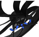
Cooling via Forced air convection for both the BLDC and ECM: BLDC Motor Cooling:
A small centrifugal fan found in the hub facilitates the BLDC to dissipate heat. Heat is dissipated though the means of convection via forced air flow through the brushless DC motor. The centrifugal impeller is located in front of the motor and before the axial impeller blades. The centrifugal impeller draws air in from the rear of the motor, away from the heat exchanger. Air then passes between the stator and magnets affectively cooling both. The air exits from the front of the motor through openings in the hub. This design results in the following: first, cooler air is supplied by drawing air furthest away form the heat exchanger. Second, the centrifugal fan found in the front of motor rotates during operation draws air through the cooling ducts. In addition, lower static pressure is created between the axial fan and the heat exchanger during the axial fan's operation aids in the flow of air.
Electronic Control Module (ECM) Cooling:
The Electronic Control Module (ECM) is placed on the edge of the shroud on a flat base plate. The ECM contains several critical components that operate the fan. It contains the brushless motor controller, heat sink, speed control, on/off fan switch (connects to vehicle's computer) and connectors. The heatsink is mated to critical, high electrical current & high temperature integrated circuits (ICs) By separating the motor and controller, the heat generated by the stator does not transfer over to the controller and vise versa. There by reducing the operating temperature of the controller and extending its operation. In addition, cooling the ECM is further facilitated via forced air convection cooling. The focused convection cooling ducts (FCCD) further decreases operating temperature. Air will flow past the heat sink, through the FCCD and through the shroud. Air enters furthest away from the heat exchanger and vehicle’s heat source. As a result, air that is focused past the heat sink fins will be cooler and allow the controller to operate at lower temperatures. Air flow through the FCCD is facilitated via the static pressure created by the main axial fan during operation. This design affectively cools the component for efficient and reliable operation. In addition, situating the ECM in this mannar reduces the air flow consumed and reduces the area obstructed to cool the ECM vs other controller cooling designs. PCB design, component placment, heatsink, module construction techniques, coupled with the FCCDs to facilitate critical electronic component cooling expand the operating life of the ECM.This allows for direct replacment in high temperature, underhood applications where higher efficinecy, longer life, lower EMI and higher performance is desired.